
Electrical Troubleshooting Guide: A Complete Playbook for Industrial Maintenance Teams
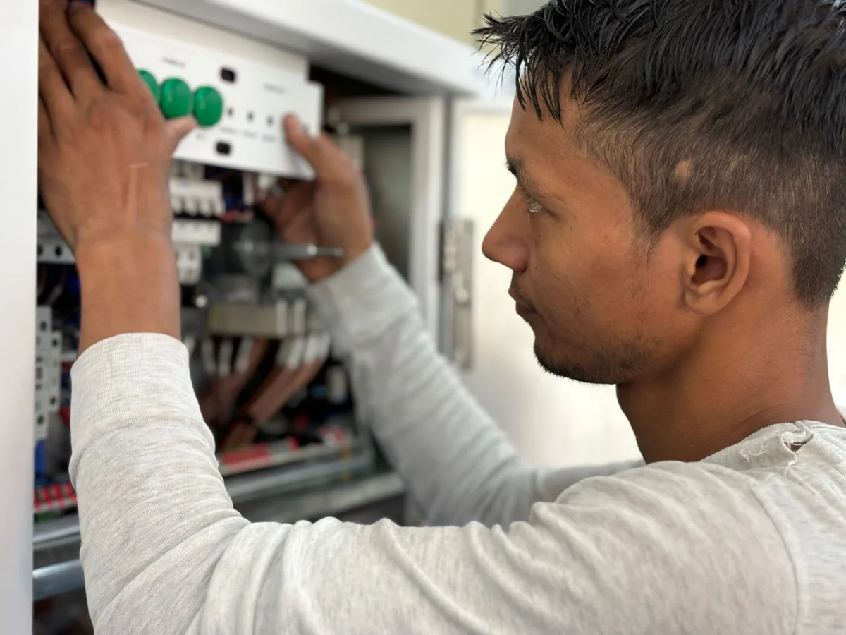
Industrial electrical troubleshooting is a systematic process for confirming a fault, comparing expected and actual conditions, isolating the affected circuit or component, identifying the root cause, and verifying the approved repair. This guide helps plant managers and L&D directors build that process across maintenance teams while giving individual technicians a practical diagnostic framework.
A consistent process helps technicians separate symptoms from causes, compare expected conditions with actual measurements, and document what they find. ITC Learning has supported industrial workforce development for more than 50 years. Explore electrical troubleshooting training for your team to build stronger knowledge of electrical systems, prints, test instruments, motors, controls, and PLCs.
What Is Industrial Electrical Troubleshooting?
Industrial electrical troubleshooting is a systematic process for finding why a machine, circuit, or control system no longer operates as intended. Technicians confirm the symptom, review the expected operation, collect evidence, isolate the fault, identify its root cause, and verify that the approved repair restored normal operation.
Troubleshooting is different from simply replacing a failed component. A blown fuse, tripped breaker, VFD alarm, or open overload contact provides evidence, but it does not always identify the main cause. For example, replacing a blown fuse may restore power without correcting the short circuit, damaged wire, or overloaded electrical load that caused it to open.
The following terms help maintenance teams separate each stage of the process:
| Term | Meaning |
|---|---|
| Symptom | What an operator or technician observes |
| Fault | The condition preventing correct operation |
| Failed component | A part that can no longer perform its intended function |
| Root cause | The underlying condition that produced the failure |
| Repair | The approved corrective action |
| Verification | Evidence that the equipment now works correctly |
This distinction matters because several electrical problems can produce the same symptom. A motor that will not start may have a failed winding, missing control voltage, open interlock, tripped overload, VFD fault, or mechanical load problem. Effective electrical fault finding follows the evidence until the team can support its conclusion.
Establish Safe Conditions Before Troubleshooting
Troubleshooting must begin with the facility’s applicable safety procedures, energy-control program, and authorization rules. Technicians need to identify the equipment’s energy sources, understand their work boundaries, select properly rated test instruments, and determine whether they can establish an electrically safe work condition before taking measurements.
Online training can strengthen technical knowledge, but it does not authorize an employee to conduct electrical work. It also does not replace site-specific training, supervised hands-on experience, licensing requirements, equipment instructions, or an employer’s process for determining who is qualified for a task.
Answer Safety Questions Before Testing
A technician should pause and establish the conditions of the job before opening an enclosure or using a meter. That preparation should address several questions:
- Is the technician qualified and authorized for this task?
- What electrical, mechanical, pneumatic, hydraulic, thermal, or stored energy could affect the work?
- Can the equipment be placed in an electrically safe work condition?
- Which facility procedure applies?
- Are the meter, leads, insulated tools, and personal protective equipment suitable for the task?
- What does the equipment manufacturer require?
- Are exposed wires or live parts present?
- What conditions require the technician to stop and escalate the problem?
The Occupational Safety and Health Administration’s (OSHA) hazardous-energy standard, 29 CFR 1910.147, covers servicing and maintenance where unexpected energization or the release of stored energy could injure an employee. Before beginning work, technicians should follow their facility’s lockout/tagout procedures and task-specific safety requirements rather than relying on a general instruction to “follow lockout/tagout.”
OSHA’s lockout/tagout standard addresses hazardous-energy control during covered servicing and maintenance. Electrical testing and work on or near energized parts are also subject to applicable electrical-safety requirements, including 29 CFR 1910.333 and 1910.334. Technicians must follow the facility’s procedures for qualification, de-energization verification, test-equipment selection, and energized work.
Electrical Troubleshooting Guide: The 10-Step Process
A reliable electrical troubleshooting process moves from a reported symptom to a supported conclusion. Individual tests will change based on the equipment, but technicians should consistently gather information, understand normal operation, compare expected and actual conditions, isolate the fault, identify its cause, and document the outcome.
1. Gather Information
Start troubleshooting by asking what happened before touching a component. Speak with the operator, review available alarms, and determine when the system failure began.
Useful details include:
- The reported symptom
- Equipment state when the failure occurred
- Fault or alarm codes
- Recent maintenance or repairs
- Process or product changes
- Previous failures
- Temperature, moisture, dust, or vibration
- Whether the fault is constant or intermittent
This step can quickly narrow the search. If a motor began tripping after a coupling or bearing replacement, for example, the driven load deserves attention alongside the electrical system.
2. Confirm the Symptom
Verify what the equipment does and does not do without creating a safety hazard. “The conveyor is down” is not specific enough. Determine whether the control system has power, the starter receives a command, the motor turns, or the conveyor moves and then stops.
The confirmed symptom creates a clear starting point. It also prevents the team from spending time on an inaccurate or incomplete report.
3. Review the Documentation
A wiring diagram, ladder diagram, sequence of operation, equipment manual, or prior work order can show how current flows and which conditions must exist before a device operates. Without that information, technicians may test components in a random order.
Review the source, control, load, and feedback paths. For PLC- or VFD-controlled equipment, also check fault history, program status, and recent parameter or logic changes when access is authorized.
4. Establish Safe and Authorized Test Conditions
Follow the facility’s energy-control and electrical work procedures before inspecting or measuring a circuit. Identify every relevant energy source and account for stored energy.
Resistance and continuity tests generally require a de-energized circuit, while voltage measurements may require stricter procedures and additional authorization. Opening one circuit breaker does not necessarily remove every energy source.
5. Divide the System Into Functional Sections
Breaking complex industrial machinery into smaller sections makes electrical fault finding more manageable. A useful model includes:
- Source: Incoming power, disconnects, transformers, circuit breakers, and fuses
- Control: Push buttons, safety devices, PLC logic, relays, and contactor coils
- Load: Motors, solenoids, heaters, and other electrical loads
- Feedback: Sensors, switches, encoders, and communication signals
If the source is healthy but the contactor never receives control voltage, the team can focus on the control path. This prevents unnecessary testing on other components.
6. Identify Expected Conditions
Before measuring voltage, current, or resistance, determine what value or state should exist. Use electrical prints, equipment ratings, manufacturer instructions, PLC logic, and the sequence of operation.
A meter reading has little value without a reference. Finding 0 volts at a motor starter coil could indicate a fault, but it could also reflect a normal stop condition or an open safety interlock.
7. Inspect and Measure Systematically
Begin at a known point and follow the circuit or signal path. A visual inspection may reveal loose connections, heat discoloration, corrosion, damaged insulation, exposed wires, contamination, or a broken wire.
Next, use the right tools to test each likely fault area. Compare every result with the expected condition and record where the first meaningful difference appears. Avoid moving randomly among unrelated test points.
8. Isolate the Fault
Technicians can trace from the source toward the load, follow a control sequence, compare input and output conditions, or divide a circuit into sections. The best method depends on the equipment and available evidence.
For complex problems, a half-split method can reduce the search area. Testing near the middle of a functional path shows which half still contains the fault, allowing the technician to narrow the problem through additional measurements.
9. Identify and Correct the Root Cause
Once the team finds a faulty part, ask why it failed. Loose wiring may create heat that damages a terminal. A mechanical bind may make a motor draw excessive current. Repeated starts may contribute to overheating. Complete only repairs allowed by the technician’s authorization and facility procedures.
10. Verify and Document the Result
Test the equipment under the conditions that originally produced the fault when it is safe and practical to do so. Confirm that protections, interlocks, and other components remain properly connected and working correctly.
Document the symptom, readings, identified fault, root cause, corrective action, and final result. Good records help another shift respond faster if the electrical issue returns.
Common Electrical Faults and What They Indicate
Industrial electrical faults generally involve an unintended break, a low-resistance path, abnormal current, poor supply conditions, or an unstable connection. Recognizing the fault category can help technicians narrow the diagnostic path.
An open circuit stops current from completing its intended path. Short circuits create an unintended low-resistance path, while ground faults allow current to follow an unintended path to ground. Overloaded circuits and voltage imbalance can also produce excess heat, blown fuses, or tripped protective devices.
| Fault type | Typical symptom | Possible causes | Useful evidence |
|---|---|---|---|
| Open circuit | A device does not energize | Broken wire, open contact, failed coil, loose terminal | Voltage-path testing and authorized continuity checks |
| Short circuit | A fuse or circuit breaker opens rapidly | Insulation damage, crossed conductors, failed component | Isolation, inspection, and resistance testing |
| Ground fault | The protective device operates, or current follows an unintended ground path | Moisture, contamination, insulation failure | Insulation testing and circuit isolation |
| Overload | Equipment runs before the protection opens | Excessive load, binding, phase loss, incorrect setting | Current measurements and load condition |
| Voltage imbalance | A three-phase motor runs hot or draws uneven current | Supply variation or loose connections | Phase-to-phase voltage and current |
| Intermittent fault | Failure appears only under certain conditions | Heat, vibration, corrosion, contamination | Fault history, trend data, and operating conditions |
A protective device should receive immediate attention when it repeatedly opens. Simply resetting tripped breakers or replacing blown fuses can erase clues and expose the equipment to the same fault again.
Which Electrical Troubleshooting Tools Should Teams Use?
Tool selection depends on the circuit, expected condition, equipment state, and diagnostic question. Multimeters, clamp meters, insulation testers, thermal imaging devices, and manufacturer software each provide different forms of evidence.
Before testing, inspect the tool, leads, and accessories and confirm that their ratings and settings suit the installation and task.
| Tool | What it helps evaluate | Important limitation |
|---|---|---|
| Digital multimeter | Voltage, resistance, continuity, and other supported measurements | Meter category, function, range, and leads must suit the task |
| Clamp meter | Current without opening the conductor | Jaw placement and conductor selection affect accuracy |
| Insulation resistance tester | Insulation condition in cables and windings | Test voltage can affect connected electronic components |
| Non-contact voltage detector | Initial indication of an energized conductor | It does not replace the required absence-of-voltage test |
| Thermal imaging device | Unusual heat patterns | Heat identifies a condition, not automatically its cause |
| PLC software | Logic states, faults, inputs, and outputs | Proper access and program knowledge are required |
| VFD interface or software | Fault history, parameters, and operating data | Menus and procedures vary by manufacturer |
Technicians should also verify that the test instrument operates as required.
How to Troubleshoot Electrical Systems With a Multimeter
A multimeter helps technicians compare the condition at a test point with the expected condition shown in the wiring diagram, sequence of operation, or manufacturer’s documentation. Define the diagnostic question before taking a measurement.
The following table connects frequent diagnostic questions with the type of evidence a technician may need:
| Diagnostic question | Measurement or tool to consider | What the result may show |
|---|---|---|
| Is the expected supply voltage present? | Voltage measurement | Whether power reaches the test point |
| Where does voltage stop along the control path? | Sequential voltage measurements | The section containing an open condition |
| Is a de-energized path open or complete? | Authorized continuity or resistance test | Whether the path provides continuity |
| Is a motor drawing uneven current? | Clamp meter | Current differences among phases |
| Has cable or winding insulation deteriorated? | Insulation resistance tester | Possible insulation weakness |
| Is a connection producing unusual heat? | Thermal imaging followed by electrical testing | A location that needs further investigation |
When measuring voltage, technicians usually place one lead at a reference point and the other at the selected test point, following the equipment documentation and approved procedure. Lead placement varies by circuit, so a generic instruction such as placing the black lead on any ground terminal may produce an incorrect or unsafe test.
A multimeter reading identifies a condition, not automatically its cause. Zero volts at a contactor coil could result from an open stop device, missing control power, an unsatisfied interlock, a broken wire, or the normal state of the circuit. The technician must follow the schematic and locate the first point where the actual condition differs from the expected one.
How Troubleshooting Changes by Equipment Type
The same evidence-based framework applies across industrial electrical equipment, but each system provides different diagnostic clues. PLCs display logic and input-output states; VFDs store faults and parameters; motors require electrical and mechanical checks, and control circuits depend on a sequence of switches, contacts, coils, and interlocks.
PLC Troubleshooting
Start PLC troubleshooting by confirming the machine state and reviewing processor, power supply, communication, and module indicators. Then compare the physical field-device state with the corresponding PLC input. An active sensor that does not register at the input may point to field power, wiring, a terminal, or an input-channel problem.
When an output indicator is active but the connected device remains off, compare the PLC state with the voltage at the output and the field device. Also check interposing relays, fuses, terminals, and return paths. If the output never turns on, review logic conditions, permissives, alarms, and safety interlocks before blaming the module.
VFD Troubleshooting
Record a VFD fault before resetting it. The fault code and history show what the drive detected, but they do not always identify which component caused the condition.
An overcurrent fault could relate to an aggressive acceleration setting, a motor problem, damaged output wiring, or a mechanically bound load. An undervoltage fault could begin at the supply rather than inside the drive. Review recent parameter changes, input conditions, motor information, load behavior, and manufacturer instructions.
| VFD fault category | Areas to investigate |
|---|---|
| Overcurrent | Acceleration, motor, output wiring, load, drive settings |
| Overvoltage | Deceleration, regenerative load, supply condition |
| Undervoltage | Incoming power, connections, protective devices |
| Overtemperature | Cooling, ventilation, ambient heat, loading |
| Ground fault | Motor cable, motor insulation, connected load |
| Motor overload | Actual load, current, motor data, drive settings |
| Communication loss | Network, cables, addressing, controller status |
Manufacturer procedures matter because a VFD’s pulse-width-modulated output is not a simple sine wave, and a conventional true-RMS multimeter may not read it reliably. Fluke’s guide to troubleshooting variable frequency drives with a multimeter recommends using an appropriate VFD measurement function, low-pass-filtered meter, or motor-drive analyzer when evaluating drive output.
Electric Motor Troubleshooting
A motor problem can begin in the supply, starter, motor, cooling system, or driven equipment. Check the motor nameplate and review voltage, phase balance, operating current, overload status, connections, winding condition, and insulation condition using authorized procedures.
Mechanical problems can also change electrical readings. A seized bearing, damaged coupling, blocked pump, or excessive conveyor load can increase motor current and heat even when the motor’s electrical components remain intact.
| Electrical evidence | Mechanical evidence |
|---|---|
| Missing or unbalanced phase voltage | Shaft or driven load resists movement |
| Uneven phase current | Bearing noise or vibration |
| Open or damaged winding | Damaged coupling |
| Insulation breakdown | Blocked pump or conveyor |
| Failed starter or overload component | Poor lubrication or misalignment |
Do not replace a motor based only on a humming sound, a tripped overload, or high current. Those symptoms justify further testing, not an automatic conclusion.
Motor Starter and Control-Circuit Troubleshooting
Control circuits often include stop devices, start commands, safety switches, PLC outputs, relays, overload contacts, and contactor coils. Any open condition in that path can prevent a motor starter from pulling in even when line power remains available.
When a contactor does not energize, trace the control circuit in its intended order:
- Confirm that control power is available.
- Check the stop and safety path.
- Verify the start command.
- Review permissives and interlocks.
- Measure across the coil using an authorized procedure.
- Inspect the coil and mechanical assembly if the correct voltage is present.
If the coil receives the expected voltage but the contactor does not move, the coil or mechanical assembly may be faulty. If the coil receives no voltage, continue tracing the upstream control path.
Do not manually force a contactor closed because this may bypass the control sequence or place connected machinery into an unexpected state.
Teams that need a more consistent technical foundation can use ITC Learning’s electrical troubleshooting training for your team to develop knowledge of electrical theory, print reading, test equipment, motors, controls, troubleshooting fundamentals, and PLCs.
Electrical Troubleshooting Decision Trees
Decision trees help technicians choose the next check after confirming the symptom and reviewing the equipment documentation. Each branch uses the available evidence to narrow the search.
Motor Will Not Start
After confirming the symptom, follow the power and control paths in the order shown in the equipment documentation.
Is a start command present?
- No: Check the initiating device, control logic, permissives, and interlocks.
- Yes: Determine whether the contactor energizes.
Does the contactor energize?
- No: Check for the expected voltage across the coil. If voltage is absent, trace the upstream control path. If voltage is present, inspect the coil and contactor mechanism under the approved procedure.
- Yes: Determine whether the motor receives the expected line voltage.
Does the motor receive the expected line voltage?
- No: Check the disconnect, circuit protection, contactor contacts, overload path, and connections.
- Yes: Investigate the motor and driven load.
Do not replace the motor until measurements and physical evidence support that conclusion.
PLC Output Is On, but the Device Is Off
A PLC output indicator does not prove that voltage reaches the field device. Compare the controller state with electrical conditions at each point in the output path.
Is the PLC output indicator on?
- No: Review program conditions, permissives, alarms, and interlocks.
- Yes: Check the output terminal and field circuit.
Is the expected voltage present at the output terminal?
- No: Investigate the module supply, output channel, fuse, or related module condition.
- Yes: Continue toward the panel terminal or interposing relay.
Is the expected voltage present at the panel terminal or the interposing relay?
- No: Inspect the connection between the PLC output and that point.
- Yes: Continue tracing the field wiring.
Does the expected voltage reach the field device?
- No: Inspect the wiring, terminals, connectors, and intermediate components.
- Yes: Examine the device, return path, and connected load.
Record the PLC state, test point, expected reading, and actual reading at each branch so another technician can review the conclusion.
Real-World Industrial Troubleshooting Examples
Worked examples show how technicians move from a broad complaint to measurable evidence. A useful case should document the reported symptom, expected operation, actual readings, isolated fault, root cause, approved correction, verification result, and any knowledge gap that slowed the diagnosis.
Conveyor Motor Will Not Start
An operator reports that a conveyor does not move after scheduled maintenance. Line power is available, but the starter does not pull in when the start command appears. Following the ladder diagram, the technician finds the expected control voltage before an interlock but not after it.
Inspection shows that the interlock was not reconnected properly during maintenance. The technician corrects the connection under the facility’s approved procedure, verifies the safety function, and tests the conveyor. The case demonstrates how following the control sequence can isolate a fault more reliably than checking components randomly.
VFD Trips During Acceleration
A pump’s variable frequency drive (VFD) repeatedly trips on overcurrent during startup after the driven equipment undergoes mechanical service. The technician records the fault and finds no electrical evidence of a supply or motor-winding problem.
A mechanical inspection reveals increased resistance in the driven assembly. Correcting that condition allows the motor to accelerate normally, showing that a VFD fault identifies the detected condition but not necessarily the component responsible.
How to Assess Your Team’s Troubleshooting Skills
Managers can evaluate troubleshooting ability through technical knowledge assessments, supervisor observation, practical evaluations, and maintenance records. No single method proves complete hands-on competence, but combined evidence can identify needs for targeted instruction, supervised practice, or stronger foundational knowledge.
Useful indicators include diagnosis time, repeat failures, unnecessary component replacement, escalation frequency, schematic-reading ability, tool selection, root-cause verification, and maintenance-note quality. Results should be interpreted in light of equipment complexity, access restrictions, parts availability, and production conditions.
Knowledge Assessment Versus Hands-On Evaluation
Each evaluation method measures a different part of troubleshooting capability:
| Evaluation method | What it measures | What it does not prove |
|---|---|---|
| Technical knowledge assessment | Concepts, terminology, calculations, and diagnostic reasoning | Safe practical performance |
| Supervisor observation | Process use and work behavior | Knowledge across every electrical topic |
| Practical evaluation | Performance on a defined task | Ability on unrelated equipment |
| Maintenance-data review | Team patterns and recurring outcomes | The individual cause of each result |
ITC’s guide on how to benchmark your maintenance team’s skills can help leaders define a repeatable evaluation process. ITC also provides skills assessments for your maintenance workforce that help organizations establish knowledge baselines, identify gaps, and connect results with targeted training.
Assessments should support workforce decisions rather than serve as the sole measure of qualification. A technician may understand ladder logic on a written assessment but still require supervised practical evaluation on the facility’s equipment.
Map Identified Skills Gaps to Electrical Training
Assessment-led training connects documented knowledge gaps with relevant instruction instead of assigning the same courses to every technician. A technician who struggles with wiring diagrams needs a different learning path from someone who understands prints but needs more knowledge of motor controls, PLC inputs, or test instruments.
The table below shows how frequent troubleshooting gaps can connect with targeted learning areas and intended knowledge outcomes.
| Identified gap | Targeted learning area | Intended knowledge outcome |
|---|---|---|
| Weak schematic interpretation | Electrical prints and ladder diagrams | Follow circuit and control paths more consistently |
| Incorrect meter selection | Electrical test instruments | Select suitable functions and interpret readings |
| Frequent control-circuit errors | Relays, contactors, and motor controls | Trace start-stop and interlock circuits |
| Confusion about PLC states | PLC fundamentals | Compare field conditions with logic states |
| Motor misdiagnosis | Motors and motor controls | Separate supply, motor, and load possibilities |
| Weak root-cause reasoning | Troubleshooting fundamentals | Distinguish symptoms from underlying causes |
ITC Learning’s electrical skills course library covers electrical theory, test equipment, print reading, motors, controls, low-voltage systems, PLCs, and troubleshooting fundamentals. Organizations can deliver this training through the ITC LMS or integrate SCORM-compatible content into an existing learning management system.
For Individual Maintenance Technicians
Individual technicians can use structured electrical learning pathways to identify their next area of study and continue building job-relevant troubleshooting knowledge. This foundation can help you understand how a system should operate, choose relevant evidence, and explain why your findings support a specific conclusion.
Keep a record of faults, test points, expected readings, actual readings, and lessons learned. Continue reviewing manufacturer documentation and facility procedures instead of relying only on memory. Online learning can develop technical knowledge, but it does not replace employer authorization, site-specific training, or supervised hands-on evaluation.
Build a More Consistent Electrical Troubleshooting Process
Effective electrical troubleshooting requires a repeatable process, equipment-specific knowledge, reliable documentation, and clear escalation boundaries. Technicians must understand normal operation, collect relevant evidence, compare actual and expected conditions, identify root causes, and document what they learn.
ITC Learning helps plant and L&D leaders identify knowledge gaps and build structured learning paths for industrial maintenance teams. Its electrical training covers fundamentals, prints, test instruments, motors, controls, VFDs, PLCs, and troubleshooting. Skills assessments and reporting also help managers focus workforce development on documented needs.
Explore electrical troubleshooting training for your team to build a more consistent foundation for diagnosing industrial electrical faults.
Why Organizations Choose ITC Learning
- 50+ years developing skilled-trades training
- 1M+ learners trained
- 160+ courses · 450+ lessons
- SCORM-compliant · Deliverable via ITC LMS or your existing platform
- Available in English + select courses in Spanish
- Supports manufacturers, industrial employers, educational institutions, workforce development programs, apprenticeships, and CTE partnerships