Manufacturing equipment is a mix of mechanical action and electrical control. When a machine faults, the root cause could be electrical, mechanical, or both.
Electrical troubleshooting for industrial equipment gives your team a logical framework to isolate the fault domain fast, verify system parameters, and execute precise repairs. It’s one of the most direct ways to cut downtime across your plant. This skill set sits at the core of any solid electrical maintenance training program.
What Is Electrical Troubleshooting for Industrial Equipment
Electrical troubleshooting for industrial equipment is a structured, step-by-step methodology to identify and resolve faults in complex manufacturing systems.
It goes beyond simple component testing. Techs evaluate the full operational system: power distribution, logic controllers, input sensors, and output actuators.
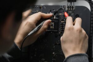
The process uses schematics, digital multimeters, and HMI diagnostic screens to trace electrical signals through the system. The goal is to narrow down potential failure points through deductive reasoning and execute repairs with confidence.
The Six-Step Process
- Recognize the symptom: Talk to the operator. Observe what the equipment does and doesn’t do.
- Define the fault domain: Is it power-related, control-related, or a mechanical issue that looks electrical?
- Trace the logic: Use schematics to find the specific circuit responsible for the failure.
- Test and verify: Use a multimeter to check voltage and continuity along the circuit path.
- Isolate and repair: Identify the faulty component and execute the repair safely.
- Test for normal operation: Confirm the equipment runs correctly and the repair didn’t create new issues.
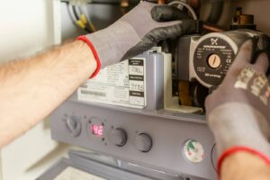
Industrial Sensor Diagnosis
Sensors are the eyes and ears of your automation system. They fail constantly in harsh plant environments.
When a VFD drive won’t start a motor, a misaligned photo-eye might be the actual cause. Your tech needs to verify physical sensor alignment, clean the lens, confirm 24VDC supply power, and test the output signal back to the PLC. For more on how motor and drive faults connect to sensor failures, see our guide on electric motor troubleshooting.
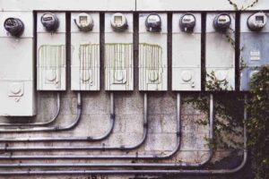
Power Distribution Problems
Loose terminations in a distribution panel create high-resistance connections that cause voltage drops under load. A machine runs fine empty, but faults the moment material hits the line.
This behavior confuses techs who don’t know what to look for. Thermal cameras spot hot connections before they fail. Multimeters measure voltage drops across fuses and disconnect switches to confirm stable power delivery. For a deeper look at what these connection failures lead to, see our guide on common electrical failures in industrial equipment.
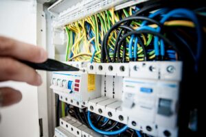
PLC Diagnostics
The PLC is a diagnostic tool, not just a black box. Watch the input and output LEDs on the PLC cards. If a limit switch is physically pressed but the corresponding input LED is off, the fault is in the field wiring or the switch itself, not the program.
This simple check saves hours of unnecessary program analysis. For more on diagnosing the motor control circuits that PLCs govern, see our guide on motor control troubleshooting.
Safety During Live Diagnostics
Live electrical troubleshooting is dangerous. Your team needs rigorous NFPA 70E training.
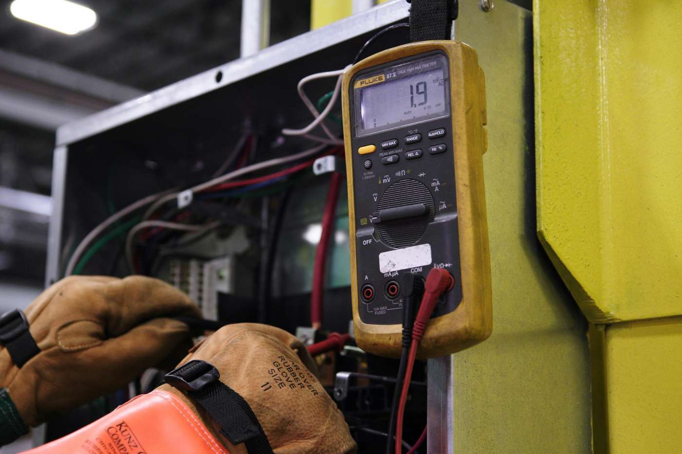
That means: correctly rated multimeters for the environment, proper arc flash PPE, and a clear understanding of when to de-energize a circuit versus test it live. For the specific skills that support safe electrical work, see our guide on electrical skills for maintenance technicians.
Recommended ITC Learning Courses
- Troubleshooting Skills: Teaches systematic diagnostic logic and structured problem-solving for any equipment type.
- Electrical/Electronic Test Equipment: Covers safe and accurate use of multimeters, meggers, and oscilloscopes.
- Programmable Logic Controllers: Builds PLC I/O diagnostic skills for fault isolation in automated systems.
- Electrical Theory for Troubleshooters: Provides the electrical theory foundation needed to understand circuit behavior during fault conditions.
- Electrical Print Reading: Builds schematic and ladder diagram fluency for fast circuit tracing.
Key Takeaways
- Electrical troubleshooting follows a strict six-step process, not guesswork.
- Sensors fail often and need systematic power, alignment, and signal output checks.
- Voltage drops from loose connections cause confusing, intermittent machine behavior.
- PLC I/O LEDs are your fastest tool for separating field device faults from controller faults.
- Live electrical diagnostics require arc flash PPE and correctly rated test equipment.
Want to build faster, safer fault diagnosis across your maintenance team? Contact ITC Learning to explore electrical troubleshooting training for your plant.
Frequently Asked Questions
-
What is the most important step in electrical troubleshooting?
Symptom recognition and information gathering. Understanding exactly what the machine was doing before the fault, straight from the operator, saves hours of blind diagnostic time.
-
How do you troubleshoot a proximity sensor?
Verify the correct supply voltage first (usually 24VDC). Then present a target to the sensor and use a multimeter to confirm the output signal switches back to the control panel.
-
Why does schematic reading matter?
Schematics are the map of the electrical system. Without them, tracing a fault through hundreds of identical wires in a complex automated machine is nearly impossible.